Water Hammer and Surge Tanks Cive 401 Mahanna Loeb Magalhaes 11192014 fWater Hammer Water Hammer is a pressure surge or wave that occurs when there is a sudden momentum change of a fluid the motion of a fluid is abruptly forced to stop or change direction within an enclosed space Water Hammer. We are currently designing a 164MW hydro electric power plant with gross head of 295m Qd727cms pipe dia 13m which involes wier conveyance line surge tank penstock line and power plant.
Surge Tank Working And Types Chemical Engineering World
In this video we will discuss on surge tank and design of it in hydropower engineeringDo like and subscribe usAny problem do message me in my instagram a.
. Surge tank details. Pipe line diameter 15 ft. Hello Arti The headloss coefficient will represent the headloss through the riser pipe connecting the surge tank to the main systemThis link which Jesse mentioned above has some general information on thisIt is largely up to the engineer to decide the value to use.
Figure 934-6 Surge Tank Vertical and Cross Section9-28 Figure 934-7 Water Level in the Surge Tank at. Results of this study indicated that for the surge tank design with D 6 m and d 34 m head pressure fluctuations reached minimum level. In which is the height at any instant of the Surge Tank level with reference to the reservoir level and are constants the former having positive values when the flow along the pipe-line is towards the Surge Tank and negative when reversed.
In addition in the case that a surge tank is constructed deep under the ground such as a tailrace surge tank the diameter of vertical shaft can be reduced by adding upper. When needed surge tanks can provide a critical feature to the hydraulic design of hydropower projects. Surge tanks are categorized in following 4 types.
One of the important parameters in the design of surge tanks is the maximum and minimum water level within the tank. A Design Example for a Circular Concrete Tank PCA Design Method CVEN 48304434 University of Colorado Boulder Spring Semester 2008 Prepared by Ben Blackard. This document describes design formulas and design example of restricted orifice surge.
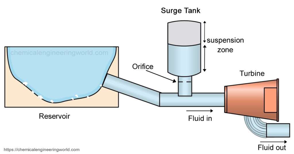
To absorb the abnormal pressure decrease in the tunnel by supplying water when rapid increase of discharge. Intermediate liquid storage tanks surge tanks are commonly installed between processing areas of the plant. The design in the Study is carried out at more detailed level than conducted in a feasibility study on a hydropower project in accordance with SW for the Study.
This article deals primarily with surge chambers in hydroelectric power plants but brief reference is also made to surges in pipelines see Appendix 1. Any imbalance in the area production rates within a plant will be reflected by. In a hydroelectric power plant or in a pumping station in order to avoid sudden large increase of pressure due to instantaneous valve closure sometimes a surge tank can be installed.
Circular Tank Example H 16 ft D 90 ft t 6 ft grade groundwater table fluid density inside tank 65 pcf f. Under normal operating conditions these storage buffers allow each process area to be operated independently of the other process areas. If the entrance to the surge tank is restricted by means of an orifice it is called an orifice tank.
- 150 - University Bulletin ISSUE No15 Vol. This type can ffely attenuate amplitude of the water level in the tank and has comparatively simple design. The theoretical treatment of oscillation in a surge tank is difficult because of the.
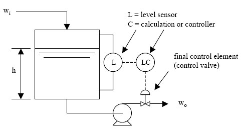
For example lets suppose the pumps ran on-off from a level-controller in the tank like a condensate pump. In addition a surge tank must have continuously running pumps. Inlet pipe 3inch NB.
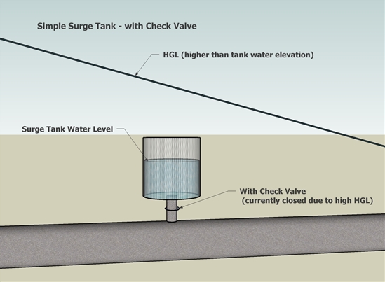
There are two main advantages in using a closed surge tank compared to the open type. Principally they can mitigate the overpressure effects of. Failure to operate the pumps continuously negates the purpose of the modulating valve.
Main outputs of the basic design are. Inlet pipe location from the bottom of the tank 1248 mm client want this at 1100 mm if possible attach the total process design calculations involved in surge tank. A surge tank has following functions.
Force during operation for linked systems with or without Surge Tanks. The three upper examples in Fig. Surge tank some of the transient pressure is transmitted to the low-pressure system.
These days Restricted Ori ce Surge Tanks are usually adopted. These pumps must pump through the modulating level-controller on the deaerator. And the length of the pipe-line from reservoir to Surge Tank.
3- 2013 2- Orifice surge tank. To absorb abnormal pressure increase in the tunnel by water hammering when load rejection or input power rejection. ــــــــــــــــــــــــــــــــــــSurge Tank Design Considerations for Controlling Water.
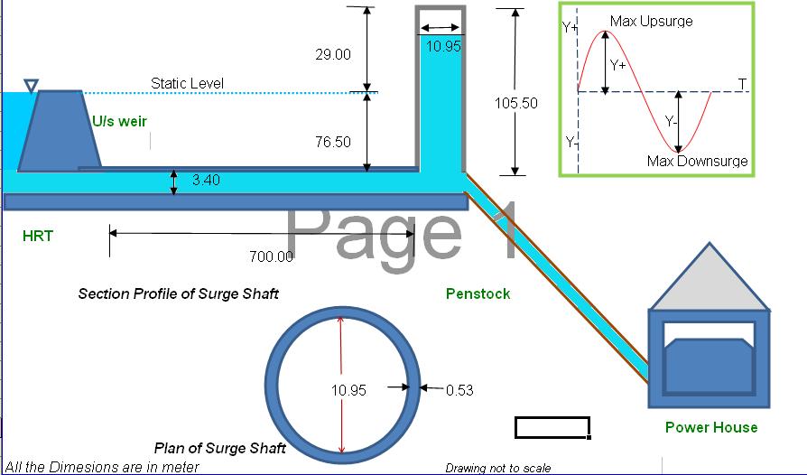
DESIGN EXAMPLE 1 340m Diameter Headrace Tunnel DESIGN EXAMPLE 2 2m Diameter Headrace Tunnel Design of surge shaft is consists of the following two parts. Choosing a Surge Tank and Determining Pressure Rise Solving for Pressure Rise when Nitrogen Gas Springs and Surge Tank is known. Find and if the Surge Tank diameter is 100 ft.
Azhary Moghaddam 2004 proposed a general solution for optimizing the maximum. The following example will help in under standing the Design criteria and procedure for Surge Shaft. 85 show traditional design with open surge tanks the lower From 1975 on shows the typical layout for a hydropower plant with a closed surge tank.
To calculate the pressure rise of a Nitrogen Gas Spring and Surge Tank system first calculate the internal volume of the gas springs where V GS. The height of surge tank is designed by the highest possible water level during the operation. I need some advice and referencespreadsheet in designing a surge tank especially the height.
Modeling Reference Surge Tanks Openflows Water Infrastructure Wiki Openflows Water Infrastructure Bentley Communities
Hydraulic Design Of Surge Shaft Definition And Design Of Surge Shafts

Surge Tanks Surge Pipes Fluid Mechanics Engineering Reference With Worked Examples

Surge Tank Control Modeling And Control
6 1 Surge Tank Model Engineering Libretexts

Design Of Surge Tank Shaft Water Hammer Effect Hydropower Engineering Ioe Tu Pu Youtube

Pdf Surge Tank Design Considerations For Controlling Water Hammer Effects At Hydro Electric Power Plants
Modeling Reference Surge Tanks Openflows Water Infrastructure Wiki Openflows Water Infrastructure Bentley Communities
0 comments
Post a Comment